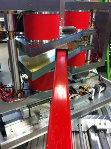
 We have tested the movement and locking system on the magnet. This appears to work better than expected. After this we even changed the gearing ration so it will move a bit faster than in the short movie made by Ernst…
 We have tested the movement and locking system on the magnet. This appears to work better than expected. After this we even changed the gearing ration so it will move a bit faster than in the short movie made by Ernst…
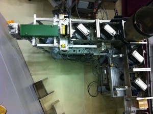 Thanks to a big effort from our student Maurice we just measured the first oscillations that are the signature of LARMOR diffraction. On the photo the 4 RF flippers create a B-field parallel to the crystal plane in the sample (inside tube), HOPG in this case. Below on the left we can see the result of a scan with the position of the last RF flipper. On the right a similar result is found for a frequency scan of the last RF
 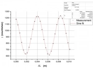 flipper.
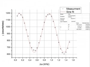
The measurements are performed on a test beam line position at the RID (between the ROG and PEARL. The key components, the RF flippers and mu-metal boxes, are origination from FLEX in Berlin so many thanks to Dr. Habicht and Dr. Keller for this opportunity to gain some experience with these components.
We are buildin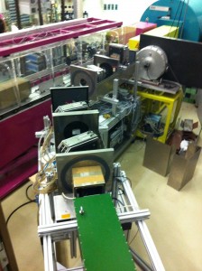 g a High Resolution Larmor Diffraction instrument in the reactor hall of RID. The key components, the RF flippers are from the FLEX Triple axis instrument. With these flippers the first Larmor diffraction experiments were performed years ago in Berlin! This is an exciting opportunity to step in this field and reproducing some of the results….
Check out the LARMOR twitter from ISIS for more on the first SANS data with the final detector…
After the magnets arrived we started a measurement of the magnetic field between the pole shoes. This was done by using a Hall probe attached on a translation stage.
The first image shows the results of a simulation, done with the help of Thomas Mouille. The second image shows the results from the real measurements (not the complete area was measured). Both graphs are normalized on the center value and use the same scale. The results show that the field is even more homogeneous than was predicted in the simulations!
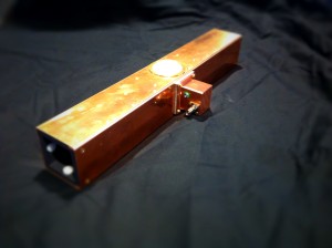 The RF flipper is almost ready to be tested. It does look pretty with all the shiny copper but there is quite some development underneath. A RF coil is fixed by epoxy in a 3D printed mold. On top is a smooth rotating disk that should act as a mechanical pickup on the magnet (later more). And we have plastic baring in a 3D printed guide/spring system to guide it along the beam tube. Soon the beam tube will come in for further testing
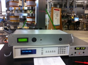 One other box that is ticked. The magnetic field regulation does work perfectly. We can set and control the magnetic field of the magnet from -100 mT to +100 mT with an accuracy of 5µT. A set-point is reached in about 5 seconds which is pretty good for such a big magnet.
We have manual and computer control available. Very pleased with the DEMO support on this!
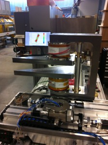 It is not the best picture, however we are very happy that the first magnet set arrived. The picture shows one half of this set that is just installed on the small rotation stage that sits on a translation stage that sits on a big rotation stage that sits on a big translation stage.
The design makes it possible to take of the pole shoes and mount it back or flip them in 7 minutes within an accuracy of….0,004 degrees!!!
With this very first installation we found some point that need attention but can be solved later. Next on the program is measuring the magnetic field and see if the simulations were realistic.
We visited the company that is producing the magnets. The tolerance on the iron yoke in quite a challenge and need a bit more work. Hopefully we can test the first magnet end of next week…